Showing posts with label home-made tools. Show all posts

How to Make a Laser Guided Angle Grinder

Over the next few weeks, I will need to cut some 4" steel pipe to fabricate a J tube rocket stove much like the one I made (here). When making the 'Rooster Rocket' I found it quite difficult to mark and accurately cut this 45° angle resulting in some scrap production and finally having to spend quite some time on grinding away the errors to attain the desired angle. So here's an idea I came up with to make life easier.


I've planned to construct a Rocket Stove Mass Heater for our lounge which will use a 5⅛" diameter steel pipe system. For both stoves I will need to part off the pipe at a 45° angle so as to produce the mitred joints creating a 90° angle when the pipes are joined.


I visited my steel supplier to check the stock of the tube I needed and to enquire about cutting the mitre when the tube was being cut to length. I was disappointed to discover that their cutting grinder was unable to provide the 45° cut on the 5⅛" pipe. Returning home I decided to come up with a method of performing this cut using my hand held angle grinder.


In the past I had made use of a light source to help me with attaining the correct angle when hand-sharpening wood plane blades and chisels (here) and this got me thinking about using some sort of bright light to act as the guide when cutting the pipe.

At the back of my tool cupboard was a spirit level with, on one end, a low-powered laser light capable of producing a point (no longer working) and on the side; a laser and lens that produced a straight line. This bright red line was ideal for producing my grinding guide.

I first constructed from pallet wood (what else?) two vee-block supports capable of holding a tube firmly in place. These supports were placed on a pallet on the floor alongside my workbench. I clamped my spirit level to the workbench so that the side which produced the laser line was facing down onto the pallet. 

Turning the laser on, the line was very clear and I could then adjust the position so that it was at 45° along the pallet deck. To determine the correct angle, I merely made sure that the line was the hypotenuse of a square I measured out on the pallet. 


The vee-block supports were placed on the pallet such that they were at right angles to the pallet edge and that the laser line was close to the left hand one - this because my stance for cutting with the angle grinder felt more comfortable oriented this way. I laid the pipe onto the vee-blocks with the laser line marking the intended cut line on the left hand end of the pipe.


I could now start cutting with the angle grinder, the cutting disc being positioned so that it entered the pipe at 90° to the pipe surface, The grinder was moved along the pipe following the guide line, always maintaining the disc angle square to the pipe face. It was possible to follow the guide line down each side of the pipe until a cut was made through half of it. 

To repeat the cut on the other side of the pipe, I repositioned the spirit level to produce the line at 45° in the opposite direction i.e. the line had been rotated through 90°. The pipe also needed to be rotated to position the underside of it for cutting. Prior to taking the pipe out of the vee-blocks I found it useful to mark with chalk the top and bottom of the pipe so that on rotating, the two marks would be once again vertically opposite each other. The pipe could be slid in the vee-blocks into the laser line such that the line was coincident with the ends of the cut made in the first step.


Once again the grinder disc was held square to the pipe surface during cutting

When the cutting was completed, I exchanged the cutting disc for a grinding disc and de-burred the cut face. 

It was quite evident that the mitre cut produced was much more accurate than my previous attempts and required very little dressing with the grinder to produce a satisfactory face to join with the next portion of pipe.

When cutting, the shadow of the grinder did block the laser light, but it was easy to make several light cuts in the pipe and after each cut to check it with the laser line. I did think that perhaps I could have traced a line in chalk following the guide line but I found it quite easy not to deviate too far from the temporarily obscured line. 

Here's the film:


If you have enjoyed this article and found it interesting then share it with your friends on social media or suchlike. Please also feel free to ask questions and or make comments and if you found this helpful and would like to support this site you can always Buy Me a Coffee at ko-fi.com =$3.


Until next time and from a sunny day in Normandie,

Cheers, Andy

 
© Andy Colley 2021
 

RELATED ARTICLES

How to make an artistic 'J' Rocket from scrap - Rooster/Cockerel Rocket

This year I decided to improve the design of our old rocket stove by changing the pipe configuration to a 'J' - tube rocket. The advantage of this format was that the fuel...read more


A Simple Home-made Honing Guide for Plane Irons & Chisels  1 

Maybe a shudder runs down your spine at the thought of school geometry but there is an elegance in being able to reproduce angles very accurately and with...read more

A Simple Home-made Honing Guide for Plane Irons & Chisels 2

This method is to enable the beginner at sharpening to get a feel for the correct sharpening angle by using a home-made low-cost guide...read more

A Simple Home-made Honing Guide for Knives

This time for knife sharpening - to enable the beginner to get a feel for the correct angle by using a home-made low-cost guide...read more

Accessory for my Simple Home-made Honing Guide for Knives

For the smaller blade on my Swiss Army Knife,it is harder to keep the straight edge against the flat face of the blade so... read more


Home-made Router Table from Scrap

I have several jobs lined up over the next few months which will involve the use of a router. These include making several wooden doors. Much of the planking I will be using will need to have moulded edges so I thought that mounting the router on a table would enable me to process them more accurately, easily and quickly.

Homemade router table

This is the finished router table in use.

Introduction


Router table from scrap wood
I have a plunge router and I use it mainly for producing decorative edges or rounding off square-cut edges for comfort (see the dry toilet seat for this very important finishing touch) . From time-to-time I would like to have the router fixed to a table with the cutting bit uppermost. This so as to enable me to better guide the wood being machined, often the case when the wood is quite narrow.

Some years ago I made a very crude attempt at holding the router in this orientation and although I successfully obtained an end result, I was not satisfied with the arrangement.

Design


I decided that the router table could be put onto a workbench or a Workmate when in operation and not a permanent fixture in the workshop. The router was to be attached to a thin mounting plate, the whole assembly would fit into an appropriate hole in the table top. The top of the table would be wide enough to allow the fitting of guides.

Construction


Scrap wood for router table
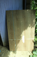
I considered that the simplest construction was for the table to be fabricated from four panels of chipboard which, whilst not being economic in material or weight, would furnish a rigid structure. As luck would have it, a non-standard size pallet came my way the top of which was covered in a sheet of plastic-coated chipboard. Once removed from the pallet, this sheet was found to be smooth and flat, a perfect surface for the table-top.

The first stage was therefore to cut the four pieces and for this I used the circular saw and guided the saw with a batten clamped to the workpiece.


Router Table component
For the router mounting plate fate was once again on my side, as I acquired a thinner (7.5mm) sheet of plastic coated board. I determined the size for the mounting plate by measuring the maximum distance between the machine’s handles as one dimension and the diameter of the router baseplate as the other dimension. To both these measurements I added 20mm. This was because the hole in the router table would need to be at least these 2 dimensions and the mounting plate would need to be bigger so as to fit onto a ‘ledge’ cut into the table top.

Preparing the components for the homemade router table
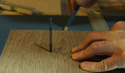
Once cut to size, I determined the centre of the rectangle and drilled a 4mm pilot hole through the piece. I then determined where the mounting plate was going to fit in the table top. This was in the middle of the long axis of the table but was off-centred at right angles to this owing to my needing space to attach guides. When I’d marked the position for the centre of the mounting plate I drilled through the table top with the 4mm drill. Thus I could then align the hole in the plate with the hole in the tabletop and use the 4mm drill bit inserted through the two holes to hold the mounting plate in the correct position. I used a try-square against the table top edge to ensure the plate remained square whilst I traced its outline with a marker pen onto the tabletop  surface.

Making the router table
I then needed to cut a rebate to the depth of the mounting plate thickness following the inside perimeter of the rectangle I had just drawn. I used the router to do this using a 10mm bit.

Once this rebate was made, I could then cut out the inner portion of the rectangle using a jigsaw. The mounting plate was then put in place to check its’ upper face was the same as the tabletop. I then marked and drilled the plates’ screw holes.

Preparing the mounting plate for the router table
To mark the positions of the holes for attaching the router to the mounting plate I first removed the plastic face from the router base and placed it, centrally, on the underside of the mounting plate. The four relevant holes could then be marked. It was whilst I was doing this that  I realised that I would have to make provision for two screws on the router base which were proud of the cast alloy surface. The positions of these were also marked and I then cut the clearance in the mounting plate with the router. The mounting holes were drilled and countersunk.
Mounting plate for the router Router ready to be fitted into the table


The centre hole was enlarged to allow the biggest of my cutters to pass through.

The free material cut to size for the router table

Assembled router tableThe table was then assembled. I cut 4 pieces of 50mm x 25mm (2” x 1”) pallet wood to that of the table length and screwed them on the inside face of the two table side pieces along the top and bottom edges. I then stood these side pieces on their long edges and placed the bottom panel on top so that the edges of each panel were in line. Using a try-square to ensure squareness the base was screwed to the 50mm x 25mm wood. Turning the assembly over, the top of the table was then screwed in place, checking to make sure that all remained square before tightening the screws.

Test Run


Router and router table mounting plate Completed homemade router table


Once the router was attached to the mounting plate, its cable was fed through the hole in the table top and lowered into position in the rebated hole.

For a test run I needed a fence against which the wood could be guided. For this I selected a piece of  125mm x 25mm (5” x 1”) dressed and varnished pine recuperated from a shop display. I used the 10mm bit to cut a clearance slot in the middle of the wood and clamped the fence to the table top. I found this to be a very effective way to guide the stuff . The end results were very satisfactory, I found the best working height for the table was obtained by clamping it to a Workmate.

... and now if you'd like to, sit back and watch the film

All the best and thanks for dropping by. Please feel free to share this article, comment and/or ask for further information.

Until next time!


Cheers, Andy

How to make a hands-free, quick-action clamp from recuperated wood

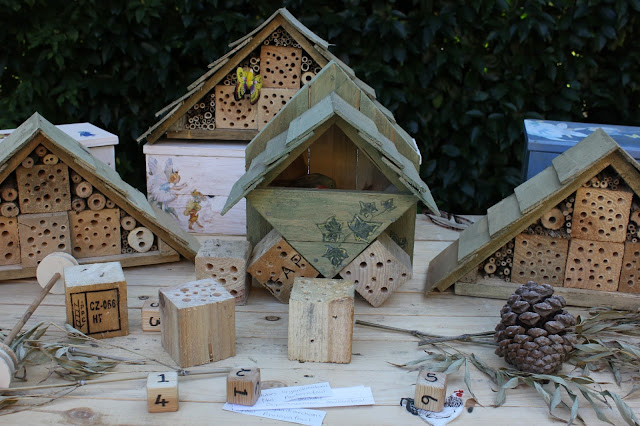
We have been invited, once again, to an ‘Art in the Garden’ event in June. We usually take along a whole host of examples of our recuperation projects some of which are for sale. The ever-popular insect houses will be displayed in their various forms and in addition, for the more Do-it-yourself visitor there will be available the drilled wooden blocks for them to make their own versions.


Insect houses at a garden exhibition

I consider the blocks to be the best way of furnishing ‘instant’ insect accommodation but they can be tedious to produce and for the ill-equiped or ‘non-DIY’er’ they are not easy to make.

Insect houses and planters from repurposed wood

Also last year I was asked to make a cover for a very ugly utilities box (3 part article here) and we came up with the idea of designing an insect hotel, which would not only hide it but also have a function within the garden. This too required a whole raft of pallet wood blocks.

Large insect hotel to cover and camouflage a utilities box

To this end, I drill several score of these recuperated un-treated wood pallet blocks which amounts to hundreds of  holes of 2 or 3 different diameters. I only have a small, short stroke hand drill drill press so I am able to drill the holes in the blocks to a depth of 50mm (2”). I then complete the drilling by hand-holding the drill, the hole continues to run vertically being guided by the pre-drilled hole. The block needs to be held during this latter operation but the time taken to secure it using conventional G-clamps or vices can make the job take twice as long.

Hands-free quick action clamp

I came up with this simple wooden clamp which is fast and effective and cost me nothing to make!

The Clamp


The device is simply a cam mounted via a pivot to a wooden baseboard. On the flat-face at the cam’s rear is an operating lever of wood 40-50cm (roughly 18”) long.

Homemade hands-free drilling clamp

The cam is made from a piece of pallet ‘stretcher’ 35mm (1½”) thick. I used a jigsaw to cut a curved face on one side of it and smoothed any irregularities with a belt sander.

detail of hand-made hands-free clamp for making insect houses

On the side of the block opposite to the curved face I screwed a length of 45mm (1¾”) x 25mm (1”) timber which acts as the operating lever. The cam was attached to the plywood base with a 6mm (¼”) x 70mm (2¾”) coach bolt. 

Explanation - parts of a pallet

A piece of pallet stringer wood 14cm (5½”) long was screwed to the baseboard opposite to the cam’s curved face., this acted as the second jaw for the clamp, the first jaw being the cam. The distance between it and the face of the cam at the cam’s minimum separation from the block was set to be just less than the size of a wooden pallet block


Operation


Detail of home-made hands-free clamp

To use the device, the base was secured to a “Workmate” workbench using a g-clamp. To prevent the device rotating when in action, the nut holding the coach bolt in place was rested against the “Workmate” jaw face such that the nut acted as a stop. 


The operating lever was extended over the front edge of the “Workmate” and moved such that the gap between the cam face and the wooden jaw was at a maximum.

Hands free clamp in operation drilling holes for insect hotel

A pallet block, pre-drilled using the drill stand, was placed in the clamp gap and the lever moved clockwise so as to bring the cam’s curved face to bear on it. Clamping force was applied and maintained simply by leaning on the lever with one’s leg, leaving the hands free to safely operate the (now hand-held) drill.

The great thing about the clamp is that as long as you’re applying pressure on the lever, the block will not move. As a consequence of the design blocks of differing sizes may also be securely held.

Now if you'd like to,
 sit back and watch the clamp in action:


Home-made insect hotel for solitary bees


All the best and thanks for dropping by. Please feel free to share this article, comment and/or ask for further information.


Cheers, Andy

Related Posts


Large luxury insect hotel
Small neat mason bee house A step-by-step tutorial for our Luxury Insect Hotel for discerning arthropods (shown left) and two simpler but effective designs for Mason bees and lacewings, follow this link for The Gîte & the Chalet (Chalet pictured right).


Crosscut Saw Table - designed and made from recuperated materials

Amongst my tools I have two portable circular saws both are regularly used but my favourite is the Makita because it is so solidly built and provides the deeper cut. This is a saw our friends used to build their boat and once that was done they no longer needed it, so gave it to us. I often need several pieces of timber of the same length and likewise need a square 90° cut. Knowing that the circular saw when correctly set can furnish the latter I just needed to come up with a way of moving the saw on a controlled path when cutting.

Crosscut saw table from repurposed materials

On one of my regular visits for pallet collection, one of my ‘suppliers’ had thrown out a steel-framed transport dolly with small castor wheels welded to it. This was transported home with the pallets as I realised the castors were the essential final part in the plan I had to onstruct a crosscut saw table.

castors from a trasport dolly - crosscut saw table

Overview

I wanted the portable circular saw to fit onto some kind of sliding table, the exposed saw blade would be beneath the table and would cut stuff held in the blade’s path. Thus the castor wheels would be screwed upside down to a baseboard and the table holding the saw would run on the castors. The table’s movement would be restricted to a forward/backward motion by guides or tracks on the underside of the table into which the castors would fit.

Crosscut saw table mock-up for the design


Method

making a crosscut saw table
The first stage was to make the moving table into which the saw’s base would fit, using a rectangular piece of plywood recuperated from a pallet top. I positioned the saw centrally and traced the outline of the saw’s base upon it. The rectangular hole was cut with the circular saw guided by a straight edge clamped to the plywood. I used a pull saw to complete the saw cuts at the four corners.
fitting the saw into the crosscut saw table


I needed to remove a little more wood from the hole edges with a rasp to obtain the snug fit of the saw’s base in the hole.>


Making guide rails for crosscut saw table


On the underside of the table I attached four lengths of wood for the guide rails. The position of the ‘inboard’ guide rails were such that about 6mm (¼”) of the guides longest edge extended over the hole edge so as to be the support for the saw base.


Checking guide rail alignment - crosscut saw table


To ensure that the rails were correctly aligned, I used the cut-out of plywood as a guide. I affixed a straight edge to the rectangle such that the inboard guide rails' edge would butt up to it, this produced the 6mm overlap of the hole's edge. 


Using castors to check crosscut saw table


Once the first inboard guide rail was glued and screwed in place, the plywood cut-out was turned around to furnish the guide for the second inboard rail. The other two guide rails were attached a castor wheels width from the ‘inboard’ guide rails.


Completed section of crosscut saw table

Recuperating castors for crosscut saw table


The castors were of the swivel type so once removed from the dolly frame I separated the castor wheel and frame from the castor base by sawing through the swivel pin.


MDF topped pallet


had selected a table base from a pallet top made of MDF which I had checked for flatness.


Castor fitted to crosscut saw table


I knew the distance the castor wheels needed tobe apart (this being the guide width on the moving table) and screwed the first pair of wheels near to the edge of the MDF base.


Castors for cross cut saw table


The other two wheels were screwed in line with the first pair of castors at a distance slightly less than half the length of the moving table.


Stops for crosscut saw table


Once I had checked that the tracks on the underside of the moving table engaged correctly with the castors and would move to and fro with ease, I screwed stops on the front and rear edges of the moving table to prevent 'derailment'.


Guide edge for crosscut saw table


The final stage was to attach a guide edge at right angles to the saws' direction of travel.


Guide regulator on crosscut saw table


This was attached to the MDF base. I made a slotted hole at one end of this guide and clamped it to the base with a wing nut so as to provide a small amount of adjustment.>


Operation

Clamping home-made cross cut saw

When I need to use the crosscut saw table, I firstly clamp the base to a 'Workmate' or workbenchThe moving table is placed onto the castors and the saw baseplate is pushed into the rectangular hole at the same time holding the blade guard in the 'open' position (blade exposed).

Exposing blade on home-made crosscut saw table

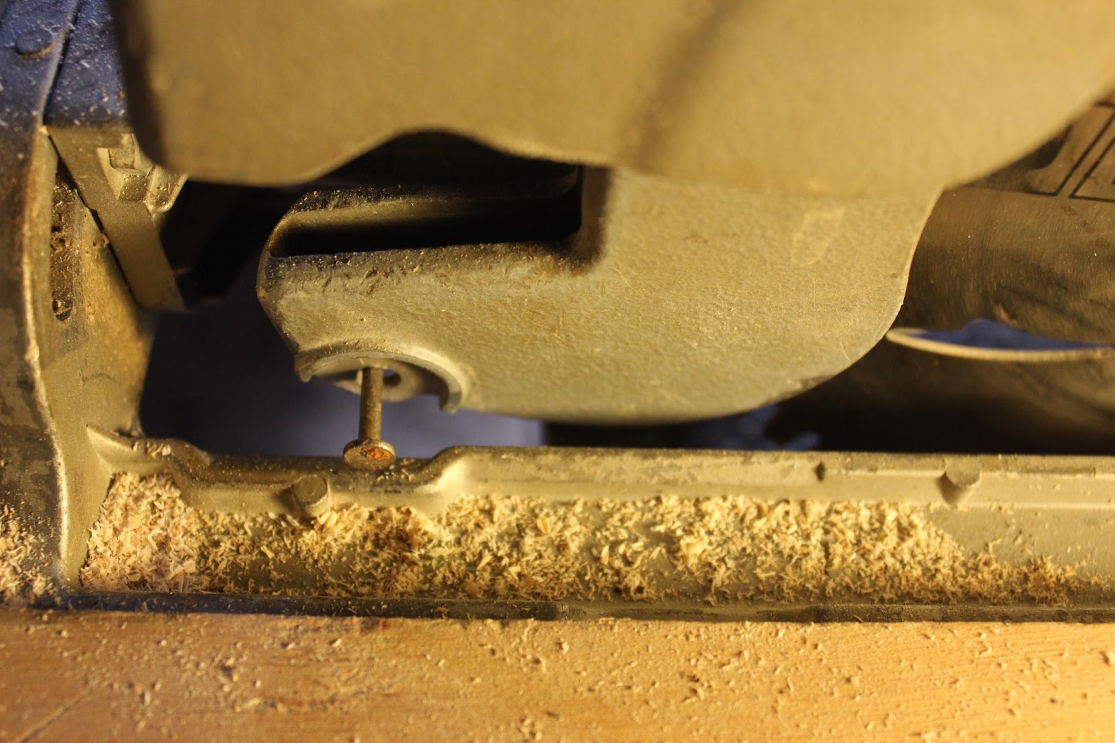
Once seated in position the guard is held open by putting a nail through a hole in the guard perimeter and letting the nail rest on the top face of the saw baseplate. Next, the saw blade cutting height is adjusted so that the blade touches the MDF table surface and then it is locked at this cutting depth.

Ensuring exact positioning home-made crosscut saw table

To cut the timber the saw is drawn back away from the guide, the timber is slid into place and held firmly against the guide edge. If I only need to cut one or two pieces of wood I mark the desired cutting point with a pencil and can see this mark through the hole in the baseplate (see image above)The stationary blade may then be brought up to the wood edge to ensure exact positioning with the mark. Moving the saw away from the edge prior to starting prevents 'snatch' .

Saw stop design for crosscut saw table
Another saw stop design for crosscut saw tableIf a greater number of equal length pieces are required I find it easier to clamp an end stop to the baseboard against which the edge of the timber can be held.

Improvements and modifications

I have definitely found the need for adding a small light over the table, specifically to illuminate through the hole in the saw baseplate so as to clearly observe the cutting marks.

Adding a light to the home-made crosscut saw table

The recuperated castors allow for a timber thickness of 50mm (2"). This I have found to fulfil my current needs but the saw is able to cut to a depth of 85mm (3¼"). To attain this one could use larger castors or raise the small castors on blocks.

Conclusion

The home made crosscut saw table has proven to be a valuable addition to the workshop and has made a robust hand power tool into a precision cutting tool at little cost. Equally important is that it may be easily and quickly converted from one form to the other.

Checking right angled cut from crosscut saw table

Now, if you'd like to, sit back and watch the film:


If you've enjoyed this article and found it useful please feel free to share it or to comment and/or make observations. All the very best and until next time,

Andy  © Andy Colley 2015
RETURN TO GREEN LEVER CONTENTS PAGE FOR MORE ARTICLES