
My first experience of re-aligning the optics in an old pair of
binoculars although successful relied heavily on a subjective
assessment of how the images could be brought into alignment by
altering the optical path through the binocular’s objective lens. I
was intrigued by how a ‘scientific’ method could produce a more
satisfactory result.


The advantage of this method is that the whole operation can be undertaken indoors and within the confines of a table measuring less than six feet by three feet.
The arrangement comprised:
- table top
- collimator
- binocular mount
- collimating scope

Here also is the link to the book, It is out of print but you can still find it: 'Choosing, Using and Repairing Binoculars' by J.W. Seyfried' is the link for the UK.
Here is the US Link: 'Choosing, Using and Repairing Binoculars' by J.W. Seyfried'
Once I got down to the
construction, however, I realised that there were several potential
problems with the layout. When I checked online for information and/or
to see if anyone else had undertaken the experiment, I could find no
evidence that it had been attempted. With our kitchen table out of
action and us having to cook and prepare meals around the set up, this
was going to be an interesting challenge on many levels.

COMPONENTS:
Table Top

It is important to note that I estimated a practicable height for the binocular support and used it as the required heights for the centre lines of the collimating scope and the collimator.
Collimator.
The most important part of this kit is the
means by which an object appears to the binocular to be at ‘infinity’. A
collimator is such a device; a cross-hair reticle is illuminated using a
low wattage light bulb. A lens placed on the other side of the reticle
at its focal length will make the light beam parallel. To the binocular,
the parallel light path appears to come from a great distance and hence
its optical elements will bring to focus in the eyepiece an image of
the reticle.

 My light box for the collimator was made from thin
(½”) pallet wood. My light source was an old garage inspection lamp from
which I had removed the bulb protection cage. This cage was attached to
the plastic body of the lamp with a metal threaded collar. I attached
the collar to the inside rim of the hole I had cut in the end wall of
the box using a Jigsaw with three short screws and could then screw the
lamp body into it. However, a bulb holder screwed to the rear wall of the box would suffice. I used an LED 6000K Bulb
My light box for the collimator was made from thin
(½”) pallet wood. My light source was an old garage inspection lamp from
which I had removed the bulb protection cage. This cage was attached to
the plastic body of the lamp with a metal threaded collar. I attached
the collar to the inside rim of the hole I had cut in the end wall of
the box using a Jigsaw with three short screws and could then screw the
lamp body into it. However, a bulb holder screwed to the rear wall of the box would suffice. I used an LED 6000K Bulb

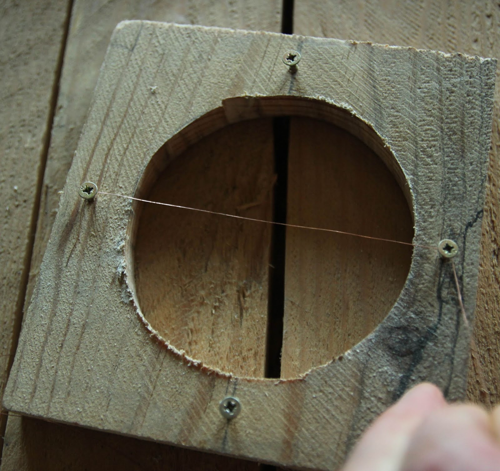
 The
reticle housing was of the same wood as the rest of the box, cut to fit
the interior width of the box with enough clearance on the width for it
to be moved towards and away from the light.. A circular hole was cut
centrally within this. I made the reticle from thin copper wire held in
place by four screws – I wound the ends of the two pieces of wire
around the screws. After the initial observations of this reticle
through the rest of the equipment, I realised that the cross wires could
not be simultaneously brought into focus due to my being unable to wind
the wires tightly enough around the screws. I changed this by soldering
the two wires together at their point of intersection and then used a
glue gun to secure the other ends to the support frame whilst keeping
each wire under tension.
The
reticle housing was of the same wood as the rest of the box, cut to fit
the interior width of the box with enough clearance on the width for it
to be moved towards and away from the light.. A circular hole was cut
centrally within this. I made the reticle from thin copper wire held in
place by four screws – I wound the ends of the two pieces of wire
around the screws. After the initial observations of this reticle
through the rest of the equipment, I realised that the cross wires could
not be simultaneously brought into focus due to my being unable to wind
the wires tightly enough around the screws. I changed this by soldering
the two wires together at their point of intersection and then used a
glue gun to secure the other ends to the support frame whilst keeping
each wire under tension.

The exit hole cut in the end wall was
made to fit a magnifying glass I had in my workshop. I subsequently
replaced this lens with a smaller, less powerful lens due to some
infuriating problems when trying to set up the apparatus. The moveable
reticle housing was fixed at a distance equal to the focal length of the
lens.

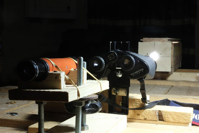
The lightbox was screwed to two supports set at a distance to rest against the inside vertical faces of the laths on the underside (now uppermost) face of the table top so that the collimator could be moved to align with either of the binocular objectives. The photograph above shows the lightbox after certain necessary modifications had taken place and these are discussed in the next article. This was a real 'thinking-on-your-feet' experiment and I didn't always remember to take images of each stage!
TOOLS: Jigsaw, Glue Gun, Soldering Iron, Screwdriver and Hand Saw
EQUIPMENT: Optical Glass Lens
Collimating Scope
Being an amateur astronomer I had to hand a
6x30 finder scope from my telescope. This has within its lens system a
cross-hair reticle ideal for aligning with the target cross wires in the
collimator. Alternatives to this would be a budget-priced telescopic
sight for a rifle.

 I made a support for the scope from pallet
wood. I’d read that the alignment method should take into account the
changes that arise when the the interpupillary distance (ipd) is altered
i.e., when the binoculars are at the extremes of their movement on the
central hinge. A change in the ipd would result in a change in the
vertical position of the optical axis of the binoculars, thus I needed
to make the height of the scope above the table adjustable. This I did
by supporting the scopes’ mounting plinth on three 10mm threaded rods.
Vertical movement was effected by screwing the nuts beneath the plinth
up or down.
I made a support for the scope from pallet
wood. I’d read that the alignment method should take into account the
changes that arise when the the interpupillary distance (ipd) is altered
i.e., when the binoculars are at the extremes of their movement on the
central hinge. A change in the ipd would result in a change in the
vertical position of the optical axis of the binoculars, thus I needed
to make the height of the scope above the table adjustable. This I did
by supporting the scopes’ mounting plinth on three 10mm threaded rods.
Vertical movement was effected by screwing the nuts beneath the plinth
up or down.
EQUIPMENT: Finder scope or Rifle scope


EQUIPMENT: Finder scope or Rifle scope
Binocular Mount
The binoculars under assessment needed to be
rigidly attached to the worktable top at a height adequate for allowing
access for adjustment either of the prisms or the objective lenses. The
mount would also have to allow the ipd to be adjusted from maximum to
minimum.
 I chose to attach the support to the binoculars using the
threaded hole in the binoculars' hinge, this is normally used for
attaching the binoculars to a tripod. I had in my ‘optical bits and
bobs’ a spotter scope tripod mounting bracket made by Vanguard (model
ref QT-30) and this I secured to a wooden support via two ¼” (6mm)
bolts. This would give me approximately ±1½” (±35mm) vertical movement,
more than enough to accommodate the change in objective centre line
height when the interpupillary distance is altered.
I chose to attach the support to the binoculars using the
threaded hole in the binoculars' hinge, this is normally used for
attaching the binoculars to a tripod. I had in my ‘optical bits and
bobs’ a spotter scope tripod mounting bracket made by Vanguard (model
ref QT-30) and this I secured to a wooden support via two ¼” (6mm)
bolts. This would give me approximately ±1½” (±35mm) vertical movement,
more than enough to accommodate the change in objective centre line
height when the interpupillary distance is altered.
EQUIPMENT: Vanguard QT-30 Tripod Mount or there are cheaper Binocular Tripod Adapters but they will need to be fitted to a vertically adjustable mount.
© Andy Colley 2018
RELATED ARTICLES


EQUIPMENT: Vanguard QT-30 Tripod Mount or there are cheaper Binocular Tripod Adapters but they will need to be fitted to a vertically adjustable mount.
In
the next article we look at the modifications needed to make this work.
If
you have enjoyed this article and found it interesting then share it
with your friends on social media or suchlike. Please also feel free to
ask questions and or make comments and if you found this helpful and would like to support this site you can always 
Until next time and from a cold day in Normandie,
Cheers, Andy
© Andy Colley 2018
RELATED ARTICLES
 Table Top Binocular Collimation Part 2 Modifications

I observed that true
to the laws of physics, once the collimator lens was set at a distance
from the cross wire reticle equivalent to the lens’ focal length and the
light was turned on, the image of the wires were in focus in the
binocular eyepiece...BUT...read more
 Table Top Binocular Collimation Part 3 The Experiment

Following
on from my previous collimation experiment, I decided that in the
Winter it would be much better to be indoors! However, this was quite a
challenge on many levels...read more
 Binocular Collimation Quick and Easy Method without Prism Adjustment

I was initially put off from correcting an optical fault in an old pair
of Porro prism binoculars because all I had seen or read online involved
prism adjustment...read more

Dear Andy
ReplyDeleteThanks for the detailed explanation and video. I have a problem in that I do not succeed in projecting the target back to the collimator. Can you please tell me what lens you used in the collimator. Your amazon reference shows no stock and unlikely to get stock. Can you please tell me what the diameter and focul length of the lens you used is.
Sincerely
Francis Cawley
Hi Francis, sincere apologies for my not replying sooner, I don't seem to be receiving notifications of comments in my mail. Anyway, it's no surprise that Amazon are not showing these products, they've let me down before - on Bader Solar Film just at the time of the total solar eclipse in the US (2017). To your important question, the lens I used was a 30mm diameter with a focal length of 145mm and was recuperated from, possibly an old pair of binoculars or an old telescope. I did find it difficult to project the image back, I had to blackout the room as my lamp intensity wasn't enough. I did try projecting the collimated image onto the wall behind the binos to establish that I was achieving a clear image of the cross wires before I even attempted to direct the image into the binoculars. The whole exercise was a series of incremental steps in establishing the process at each stage and it was quite tedious, but I was doing it inside! But for establishing of the alignment of the optics with the optical axis of the bino's body I much prefer using the 'quicker' method referred to in the 'related articles'. Hope this is of some help, but please get back in touch if you need more details.
ReplyDeleteBest Wishes from Normandie, Andy.