I have several jobs lined up over the next few months which will involve the use of a router. These include making several wooden doors. Much of the planking I will be using will need to have moulded edges so I thought that mounting the router on a table would enable me to process them more accurately, easily and quickly.
This is the finished router table in use.
Introduction
I have a plunge router and I use it mainly for producing decorative edges or rounding off square-cut edges for comfort (see the dry toilet seat for this very important finishing touch) . From time-to-time I would like to have the router fixed to a table with the cutting bit uppermost. This so as to enable me to better guide the wood being machined, often the case when the wood is quite narrow.
Some years ago I made a very crude attempt at holding the router in this orientation and although I successfully obtained an end result, I was not satisfied with the arrangement.
Design
I decided that the router table could be put onto a workbench or a Workmate when in operation and not a permanent fixture in the workshop. The router was to be attached to a thin mounting plate, the whole assembly would fit into an appropriate hole in the table top. The top of the table would be wide enough to allow the fitting of guides.
Construction
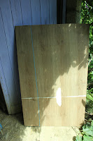
I considered that the simplest construction was for the table to be fabricated from four panels of chipboard which, whilst not being economic in material or weight, would furnish a rigid structure. As luck would have it, a non-standard size pallet came my way the top of which was covered in a sheet of plastic-coated chipboard. Once removed from the pallet, this sheet was found to be smooth and flat, a perfect surface for the table-top.
The first stage was therefore to cut the four pieces and for this I used the circular saw and guided the saw with a batten clamped to the workpiece.
For the router mounting plate fate was once again on my side, as I acquired a thinner (7.5mm) sheet of plastic coated board. I determined the size for the mounting plate by measuring the maximum distance between the machine’s handles as one dimension and the diameter of the router baseplate as the other dimension. To both these measurements I added 20mm. This was because the hole in the router table would need to be at least these 2 dimensions and the mounting plate would need to be bigger so as to fit onto a ‘ledge’ cut into the table top.
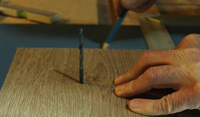
Once cut to size, I determined the centre of the rectangle and drilled a 4mm pilot hole through the piece. I then determined where the mounting plate was going to fit in the table top. This was in the middle of the long axis of the table but was off-centred at right angles to this owing to my needing space to attach guides. When I’d marked the position for the centre of the mounting plate I drilled through the table top with the 4mm drill. Thus I could then align the hole in the plate with the hole in the tabletop and use the 4mm drill bit inserted through the two holes to hold the mounting plate in the correct position. I used a try-square against the table top edge to ensure the plate remained square whilst I traced its outline with a marker pen onto the tabletop surface.
I then needed to cut a rebate to the depth of the mounting plate thickness following the inside perimeter of the rectangle I had just drawn. I used the router to do this using a 10mm bit.
Once this rebate was made, I could then cut out the inner portion of the rectangle using a jigsaw. The mounting plate was then put in place to check its’ upper face was the same as the tabletop. I then marked and drilled the plates’ screw holes.
To mark the positions of the holes for attaching the router to the mounting plate I first removed the plastic face from the router base and placed it, centrally, on the underside of the mounting plate. The four relevant holes could then be marked. It was whilst I was doing this that I realised that I would have to make provision for two screws on the router base which were proud of the cast alloy surface. The positions of these were also marked and I then cut the clearance in the mounting plate with the router. The mounting holes were drilled and countersunk.


The centre hole was enlarged to allow the biggest of my cutters to pass through.
 The table was then assembled. I cut 4 pieces of 50mm x 25mm (2” x 1”) pallet wood to that of the table length and screwed them on the inside face of the two table side pieces along the top and bottom edges. I then stood these side pieces on their long edges and placed the bottom panel on top so that the edges of each panel were in line. Using a try-square to ensure squareness the base was screwed to the 50mm x 25mm wood. Turning the assembly over, the top of the table was then screwed in place, checking to make sure that all remained square before tightening the screws.
 Test Run
Once the router was attached to the mounting plate, its cable was fed through the hole in the table top and lowered into position in the rebated hole.
For a test run I needed a fence against which the wood could be guided. For this I selected a piece of 125mm x 25mm (5” x 1”) dressed and varnished pine recuperated from a shop display. I used the 10mm bit to cut a clearance slot in the middle of the wood and clamped the fence to the table top. I found this to be a very effective way to guide the stuff . The end results were very satisfactory, I found the best working height for the table was obtained by clamping it to a Workmate.
... and now if you'd like to, sit back and watch the film
Until next time!
Cheers, Andy


No comments:
Post a Comment