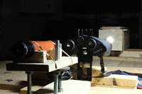
As I started setting up I observed that true
to the laws of physics, once the collimator lens was set at a distance
from the cross wire reticle equivalent to the lens’ focal length and the
light was turned on, the image of the wires were in focus in the
binocular eyepiece. This, even though they were less than 40” (1m) from
the object and that image, through the eyepiece, could be viewed
through the spotting scope. BUT I was aware that I had not ensured that
the collimated image was hitting the center of the objective nor that
the binoculars’ optical axes were parallel to the centre line of the
collimated beam both important criteria had been omitted from the book.
Nor had I established that the binoculars were parallel to the table
top.
From the above I deduced that the only point of reference
that I had was that everything had to centre on the axis of the
collimated light beam. Both the binoculars and the spotting scope would
need to be on or parallel with that axis. On this basis I concluded that
I needed a method to determine that the collimated image was coincident
with the centre of the objective lens and that I needed to use this
same image for establishing the second criteria.
To center the
image, I cut two thin cardboard discs to fit inside the dew cap of the
objective lenses. To make these, I measured the dew cap internal
diameter with Vernier calipers and used a pair of compass dividers to
scribe a circle to that diameter in the card. By continuously scribing
with the dividers, the card was eventually cut through producing an
exact card circle with a centre hole marked within.. To these two discs
I glued a piece of twine to facilitate easy removal from the dew cap.
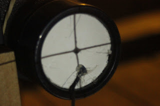
With the binoculars in place on the support I inserted the discs. I
found that I could see the shadow of the cross wires on the objective by
moving the target within the collimator box away from the collimator
lens until a sharp image could be seen on the disc. Thus I was able to
use the collimator as a crude but effective projector.
Moving the
cross wire target also highlighted the image shift if the target was not
kept vertical or if it twisted so that it did not remain perpendicular
to the walls of the light box. Before I could proceed I decided to fix
the position of the reticle so that it remained vertical and square to
the lens. Having done this I needed to make the collimator lens position
adjustable so that I could obtain:
- The collimated cross wire image as before
- A focused image of the cross wires on the discs in the dew caps.
- Additional adjustment to increase the distance of the focused image by approximately two. (This to be explained in the solution to establishing that the binoculars’ optical axis was collinear with that of the collimator).
INSTRUMENTS: Vernier Calipers, Precision Compass Dividers
In the next article we look at the experiment proper
If
you have enjoyed this article and found it interesting then share it
with your friends on social media or suchlike. Please also feel free to
ask questions and or make comments and if you found this helpful and would like to support this site you can always 
Until next time and from a cold day in Normandie,
Cheers, Andy
© Andy Colley 2018
RELATED ARTICLES
Table Top Binocular Collimation Part 1 Materials & Fabrication
Following
on from my previous collimation experiment, I decided that in the
Winter it would be much better to be indoors! However, this was quite a
challenge on many levels...read more
Table Top Binocular Collimation Part 3 The Experiment
Following
on from my previous collimation experiment, I decided that in the
Winter it would be much better to be indoors! However, this was quite a
challenge on many levels...read more
 Binocular Collimation Quick and Easy Method without Prism Adjustment
I was initially put off from correcting an optical fault in an old pair
of Porro prism binoculars because all I had seen or read online involved
prism adjustment...read more


