Showing posts with label Binocular Collimation. Show all posts

DIY Table Top Binocular Collimator - The Experiment

Table top binocular collimation
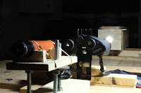
I had already established the approximate distances between the components so I screwed the binocular support to the table such that the binocular objectives would be about 90cm (36”) from the collimator lens.

The collimation scope was fitted to its mount which was on the eyepiece side of the binoculars. As I had previously mentioned, the support for this scope had a base which fitted between the table laths and could mimic the collimator's movement from side to side.

Only the collimator had a fixed vertical height, the other two components in the layout could both have their heights adjusted.

The first stage was to ensure that the collimated light source was centred on the centre line of the binocular. To do this, I inserted the cardboard discs into the dew cap rings of the objective lenses and adjusted the collimator lens so that the image of the target was visible on the one disc.

Binocular collimation with homemade collimatorBinocular alignment

It was easy to see if the cross wire centre was coincident with that of the disc centre and any discrepancies were easily rectified viz, horizontal difference slide the collimator in its guides, vertically; slacken the binocular mount locknut and move the binoculars up or down. It was also possible to slide the collimator to the other objective to confirm or otherwise that the second objective lens centre was also coincident with the collimated beam centre. The main reason why this would not be so would be that the binoculars were not level on their mount. Obviously any correction to this parameter would require the checking of the other objectives’ position until the two objectives were both centred on the centre of the light beam.

DIY collimator for binocular alignment


The next parameter to check was that the binoculars were square to the light beam i.e., they were not off-axis (tilted or skewed). This posed a problem as there was not a flat surface on the binocular body which I could use as a reference. I finally realised that the binocular dew cap rings were the only machined flat surface on the front end of the binoculars. I used this feature by securing a flat mirror over the objective lens, held flat against the dew cap ring with an elastic band stretched from the eyepiece end of the binoculars. The reflected light was then visible on the front wall of the collimator on which I had drawn a vertical and horizontal line with their intersection coincident with the lens centre. The lens was refocused. A perfectly squared binocular and hence mirror would superimpose the cross image onto the drawn lines. The arrangement was an optical lever very similar to that used in a ballistic galvanometer. The image was brought into alignment with the drawn cross by tilting and/or skewing the binocular mount. Once this was achieved, I removed the mirror and refocussed the lens so that I could check that the cross centre was still in the centre of the cardboard disc, any shift was corrected as previously described and the mirror replaced to check that squareness to the light beam had not been compromised.

Once this was satisfactorily achieved, the card discs were removed and the lens refocused once again but to the third position i.e., the one that produced the collimated beam. This was confirmed by looking into the binocular eyepiece.

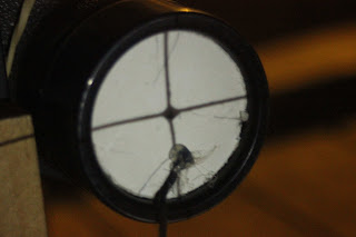
That being so the spotter scope was slid into position, looking through the binocular eyepiece and the image of the cross wire studied through it.

I had set the distance between the spotter scope and the eyepiece of the binoculars such that the image from the eyepiece was slightly smaller than the view in the scope. This was so that I could ensure the scope was looking straight into the centre of the eyepiece-the image was surrounded by an annular dark ring.

Properly aligned binoculars would give an image of the cross wires of the spotting scope superimposed on the target image.

Make your own collimation benchI had decided to correct any misalignment by adjusting the position of the objective lens within its eccentric retainer ring. To do this I had to unscrew and remove the dew cap ring. This I was able to do firstly on the right hand half of the binoculars. There was sufficient adjustment to attain the alignment of the two sets of cross wires. If there hadn’t had been enough I would have had to resort to prism adjustment.

I was also able to ensure the binoculars were still aligned to the collimator by repeating the operation with the mirror only this time the mirror was resting against the machined flat face of the binocular body and not the dew cap ring.

I then shifted the collimator to centre on the left-hand objective lens of the binoculars and moved the finder scope into position behind the eyepiece. The image in the left-hand half of the binoculars was coincident with the cross wire in the finder scope, so no adjustment was necessary in this case.

I could now remove the binoculars from their mount and look through them to see if the quality of the image had improved, which it had! The realignment process was a success.

INSTRUMENTS: Flat Double Sided Mirror

Precautions

Whilst I was checking the alignment with the mirror I leant on the table and saw the cross-wire shadow move on the front wall of the collimator by about ¼” the original position resumed as soon as I removed my weight. Don’t lean on the apparatus!

...and if you're listening Santa


..and now sit back and watch the film:


In Conclusion

I was pleased with the end results that I obtained by using this 'kitchen table' arrangement and once the initial 'teething problems' had been overcome, I found the apparatus easy to use. It would be interesting to develop an optical array that could produce two collimated images so that both sides of the binoculars could be tested simultaneously, obviating the need to move the collimator.

If you have enjoyed this article and found it interesting then share it with your friends on social media or suchlike. Please also feel free to ask questions and or make comments and if you found this helpful and would like to support this site you can always Buy Me a Coffee at ko-fi.com

Until next time and from a cold day in Normandie,

Cheers, Andy

© Andy Colley 2018

RELATED ARTICLES 

Table Top Binocular Collimation Part 1 Materials & Fabrication

Following on from my previous collimation experiment, I decided that in the Winter it would be much better to be indoors! However, this was quite a challenge on many levels...read more

Table Top Binocular Collimation Part 2 Modifications

I observed that true to the laws of physics, once the collimator lens was set at a distance from the cross wire reticle equivalent to the lens’ focal length and the light was turned on, the image of the wires were in focus in the binocular eyepiece...BUT...read more

Binocular Collimation Quick and Easy Method without Prism Adjustment

I was initially put off from correcting an optical fault in an old pair of Porro prism binoculars because all I had seen or read online involved prism adjustment...read more

DIY Table Top Binocular Collimator - Modifications to Method/Apparatus


As I started setting up I observed that true to the laws of physics, once the collimator lens was set at a distance from the cross wire reticle equivalent to the lens’ focal length and the light was turned on, the image of the wires were in focus in the binocular eyepiece. This, even though they were less than 40” (1m) from the object and that image, through the eyepiece, could be viewed through the spotting scope. BUT I was aware that I had not ensured that the collimated image was hitting the center of the objective nor that the binoculars’ optical axes were parallel to the centre line of the collimated beam both important criteria had been omitted from the book. Nor had I established that the binoculars were parallel to the table top.

Table top binocular collimation


From the above I deduced that the only point of reference that I had was that everything had to centre on the axis of the collimated light beam. Both the binoculars and the spotting scope would need to be on or parallel with that axis. On this basis I concluded that I needed a method to determine that the collimated image was coincident with the centre of the objective lens and that I needed to use this same image for establishing the second criteria.

Table top binocular alignment
Using collimator as a projector
To center the image, I cut two thin cardboard discs to fit inside the dew cap of the objective lenses. To make these, I measured the dew cap internal diameter with Vernier calipers and used a pair of compass dividers to scribe a circle to that diameter in the card. By continuously scribing with the dividers, the card was eventually cut through producing an exact card circle with a centre hole marked within.. To these two discs I glued a piece of twine to facilitate easy removal from the dew cap. With the binoculars in place on the support I inserted the discs. I found that I could see the shadow of the cross wires on the objective by moving the target within the collimator box away from the collimator lens until a sharp image could be seen on the disc. Thus I was able to use the collimator as a crude but effective projector.

DIY table top binocular collimation

Moving the cross wire target also highlighted the image shift if the target was not kept vertical or if it twisted so that it did not remain perpendicular to the walls of the light box. Before I could proceed I decided to fix the position of the reticle so that it remained vertical and square to the lens. Having done this I needed to make the collimator lens position adjustable so that I could obtain:
  • The collimated cross wire image as before
  • A focused image of the cross wires on the discs in the dew caps.
  • Additional adjustment to increase the distance of the focused image by approximately two. (This to be explained in the solution to establishing that the binoculars’ optical axis was collinear with that of the collimator). 

DIY binocular collimator lens cell
DIY table top binocular alighment
I decided to fabricate a cylindrical housing for the collimator lens and for this I used a cleaned plastic tube from a silicone mastic dispenser. I made a lens cell to hold the lens out of the plastic piston within the mastic tube and fixed this in the end of the tube using the glue gun. The end wall of the collimator box was modified to accommodate this new lens arrangement with the addition of further guides/supports attached to both the inner and outer faces of the wall.
Make your own collimator


INSTRUMENTS: Vernier Calipers, Precision Compass Dividers

In the next article we look at the experiment proper

If you have enjoyed this article and found it interesting then share it with your friends on social media or suchlike. Please also feel free to ask questions and or make comments and if you found this helpful and would like to support this site you can always Buy Me a Coffee at ko-fi.com

Until next time and from a cold day in Normandie,

Cheers, Andy

© Andy Colley 2018

RELATED ARTICLES 

Table Top Binocular Collimation Part 1 Materials & Fabrication

Following on from my previous collimation experiment, I decided that in the Winter it would be much better to be indoors! However, this was quite a challenge on many levels...read more

Table Top Binocular Collimation Part 3 The Experiment

Following on from my previous collimation experiment, I decided that in the Winter it would be much better to be indoors! However, this was quite a challenge on many levels...read more

Binocular Collimation Quick and Easy Method without Prism Adjustment

I was initially put off from correcting an optical fault in an old pair of Porro prism binoculars because all I had seen or read online involved prism adjustment...read more
.

DIY Table Top Binocular Collimator - Sourcing Materials & Fabrication

My first experience of re-aligning the optics in an old pair of binoculars although successful relied heavily on a subjective assessment of how the images could be brought into alignment by altering the optical path through the binocular’s objective lens. I was intrigued by how a ‘scientific’ method could produce a more satisfactory result.


To this end I decided to make a collimating setup similar to that described in the book by Seyfried.

The advantage of this method is that the whole operation can be undertaken indoors and within the confines of a table measuring less than six feet by three feet.

The arrangement comprised:
  • table top
  • collimator
  • binocular mount
  • collimating scope

On reading of the materials necessary to build this apparatus, I realised that I had all the items in my workshop all I had to do was put them together. However, I have provided some links to sources for tools and equipment, which I hope will prove useful.

Here also is the link to the book, It is out of print but you can still find it:  'Choosing, Using and Repairing Binoculars' by J.W. Seyfried' is the link for the UK.

Here is the US Link: 'Choosing, Using and Repairing Binoculars' by J.W. Seyfried'
 

Once I got down to the construction, however, I realised that there were several potential problems with the layout. When I checked online for information and/or to see if anyone else had undertaken the experiment, I could find no evidence that it had been attempted. With our kitchen table out of action and us having to cook and prepare meals around the set up, this was going to be an interesting challenge on many levels. 


COMPONENTS:  


Table Top 

Both the collimator and the collimating scope needed to move laterally so that the light could be directed through each half of the binocular and the effect observed. On a workbench I would have screwed horizontal rails to the top of the bench to hold the pedestal base of each of the components so that they could be moved parallel to each other. As I was using the kitchen table, I decided to place on top of it a trestle table top I made some years ago from pallet wood. This I placed upside down on the kitchen table as the pallet wood planks were nailed to four laths that would suffice as the guide rails.


It is important to note that I estimated a practicable height for the binocular support and used it as the required heights for the centre lines of the collimating scope and the collimator. 


Collimator.

The most important part of this kit is the means by which an object appears to the binocular to be at ‘infinity’. A collimator is such a device; a cross-hair reticle is illuminated using a low wattage light bulb. A lens placed on the other side of the reticle at its focal length will make the light beam parallel. To the binocular, the parallel light path appears to come from a great distance and hence its optical elements will bring to focus in the eyepiece an image of the reticle.


My light box for the collimator was made from thin (½”) pallet wood. My light source was an old garage inspection lamp from which I had removed the bulb protection cage. This cage was attached to the plastic body of the lamp with a metal threaded collar. I attached the collar to the inside rim of the hole I had cut in the end wall of the box using a Jigsaw with three short screws and could then screw the lamp body into it. However, a bulb holder screwed to the rear wall of the box would suffice. I used an LED 6000K Bulb


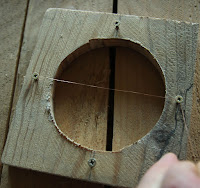
The reticle housing was of the same wood as the rest of the box, cut to fit the interior width of the box with enough clearance on the width for it to be moved towards and away from the light.. A circular hole was cut centrally within this. I made the reticle from thin copper wire held in place by four screws – I wound the ends of the two pieces of wire around the screws. After the initial observations of this reticle through the rest of the equipment, I realised that the cross wires could not be simultaneously brought into focus due to my being unable to wind the wires tightly enough around the screws. I changed this by soldering the two wires together at their point of intersection and then used a glue gun to secure the other ends to the support frame whilst keeping each wire under tension.


The exit hole cut in the end wall was made to fit a magnifying glass I had in my workshop. I subsequently replaced this lens with a smaller, less powerful lens due to some infuriating problems when trying to set up the apparatus. The moveable reticle housing was fixed at a distance equal to the focal length of the lens.


The lightbox was screwed to two supports set at a distance to rest against the inside vertical faces of the laths on the underside (now uppermost) face of the table top so that the collimator could be moved to align with either of the binocular objectives. The photograph above shows the lightbox after certain necessary modifications had taken place and these are discussed in the next article. This was a real 'thinking-on-your-feet' experiment and I didn't always remember to take images of each stage!

TOOLS: Jigsaw, Glue Gun, Soldering Iron, Screwdriver and Hand Saw
EQUIPMENT: Optical Glass Lens

Collimating Scope

Being an amateur astronomer I had to hand a 6x30 finder scope from my telescope. This has within its lens system a cross-hair reticle ideal for aligning with the target cross wires in the collimator. Alternatives to this would be a budget-priced telescopic sight for a rifle.


I made a support for the scope from pallet wood. I’d read that the alignment method should take into account the changes that arise when the the interpupillary distance (ipd) is altered i.e., when the binoculars are at the extremes of their movement on the central hinge. A change in the ipd would result in a change in the vertical position of the optical axis of the binoculars, thus I needed to make the height of the scope above the table adjustable. This I did by supporting the scopes’ mounting plinth on three 10mm threaded rods. Vertical movement was effected by screwing the nuts beneath the plinth up or down.

EQUIPMENT: Finder scope or Rifle scope

Binocular Mount

The binoculars under assessment needed to be rigidly attached to the worktable top at a height adequate for allowing access for adjustment either of the prisms or the objective lenses. The mount would also have to allow the ipd to be adjusted from maximum to minimum.


I chose to attach the support to the binoculars using the threaded hole in the binoculars' hinge, this is normally used for attaching the binoculars to a tripod. I had in my ‘optical bits and bobs’ a spotter scope tripod mounting bracket made by Vanguard (model ref QT-30) and this I secured to a wooden support via two ¼” (6mm) bolts. This would give me approximately ±1½” (±35mm) vertical movement, more than enough to accommodate the change in objective centre line height when the interpupillary distance is altered.


EQUIPMENT: Vanguard QT-30 Tripod Mount or there are cheaper Binocular Tripod Adapters but they will need to be fitted to a vertically adjustable mount.


In the next article we look at the modifications needed to make this work.

If you have enjoyed this article and found it interesting then share it with your friends on social media or suchlike. Please also feel free to ask questions and or make comments and if you found this helpful and would like to support this site you can always Buy Me a Coffee at ko-fi.com

Until next time and from a cold day in Normandie,

Cheers, Andy

© Andy Colley 2018

RELATED ARTICLES

Table Top Binocular Collimation Part 2 Modifications

I observed that true to the laws of physics, once the collimator lens was set at a distance from the cross wire reticle equivalent to the lens’ focal length and the light was turned on, the image of the wires were in focus in the binocular eyepiece...BUT...read more

Table Top Binocular Collimation Part 3 The Experiment

Following on from my previous collimation experiment, I decided that in the Winter it would be much better to be indoors! However, this was quite a challenge on many levels...read more

Binocular Collimation Quick and Easy Method without Prism Adjustment

I was initially put off from correcting an optical fault in an old pair of Porro prism binoculars because all I had seen or read online involved prism adjustment...read more